Tip: After making all the changes to the hardware of the fuselage according to your requirements, do check the Center of Gravity of the whole plane.
Wednesday, May 15, 2013
Tuesday, May 14, 2013


Monday, May 13, 2013
19. Coordinating hardware with our program
We went into the options.h file of Matrix-Pilot UDB4 and did the following changes:
(Where left columns is from the receiver and the right column on the devboard)
// Configure Input and Output Channels
//
// For classic UDB boards:
// Use a single PPM input connection from the RC receiver to the UDB on RC input channel 4.
// This frees up RC inputs 3, 2, and 1 to act as RC outputs 4, 5, and 6.
// If PPM_ALT_OUTPUT_PINS is set to 0, the 9 available RC outputs will be sent to the
// following pins, in this order: Out1, Out2, Out3, In3, In2, In1, RE0, RE2, RE4.
// With it set to 1, the RC outputs will be in this alternate configuration:
// Out1, Out2, Out3, RE0, RE2, RE4, In3, In2, In1.
//
// For UDB4 boards:
// Use a single PPM input connection from the RC receiver to the UDB on RC input channel 1.
// The 8 standard output channels remain unaffected. 2 additional output channels are available
// on pins RA4 and RA1.
//
// For all boards:
// If you're not sure, leave USE_PPM_INPUT set to 0.
// PPM_NUMBER_OF_CHANNELS is the number of channels sent on the PWM signal. This is
// often different from the NUM_INPUTS value below, and should usually be left at 8.
//
#define USE_PPM_INPUT 0
#define PPM_NUMBER_OF_CHANNELS 8
#define PPM_SIGNAL_INVERTED 0
#define PPM_ALT_OUTPUT_PINS 0
// NUM_INPUTS:
// For classic boards: Set to 1-5 (or 1-8 when using PPM input)
// 1-4 enables only the first 1-4 of the 4 standard input channels
// 5 also enables E8 as the 5th input channel
// For UDB4 boards: Set to 1-8
#define NUM_INPUTS 6
// Channel numbers for each input.
// Use as is, or edit to match your setup.
// - If you're set up to use Rudder Navigation (like MatrixNav), then you may want to swap
// the aileron and rudder channels so that rudder is CHANNEL_1, and aileron is 5.
#define THROTTLE_INPUT_CHANNEL CHANNEL_1
#define AILERON_INPUT_CHANNEL CHANNEL_2
#define ELEVATOR_INPUT_CHANNEL CHANNEL_3
#define RUDDER_INPUT_CHANNEL CHANNEL_4
#define MODE_SWITCH_INPUT_CHANNEL CHANNEL_6
#define CAMERA_PITCH_INPUT_CHANNEL CHANNEL_UNUSED
#define CAMERA_YAW_INPUT_CHANNEL CHANNEL_UNUSED
#define CAMERA_MODE_INPUT_CHANNEL CHANNEL_UNUSED
#define OSD_MODE_SWITCH_INPUT_CHANNEL CHANNEL_UNUSED
#define PASSTHROUGH_A_INPUT_CHANNEL CHANNEL_5
#define PASSTHROUGH_B_INPUT_CHANNEL CHANNEL_UNUSED
#define PASSTHROUGH_C_INPUT_CHANNEL CHANNEL_UNUSED
#define PASSTHROUGH_D_INPUT_CHANNEL CHANNEL_UNUSED
// NUM_OUTPUTS:
// For classic boards: Set to 3, 4, 5, or 6
// 3 enables only the standard 3 output channels
// 4 also enables E0 as the 4th output channel
// 5 also enables E2 as the 5th output channel
// 6 also enables E4 as the 6th output channel
// NOTE: If USE_PPM_INPUT is enabled above, up to 9 outputs are available.)
// For UDB4 boards: Set to 3-8 (or up to 10 using pins RA4 and RA1.)
#define NUM_OUTPUTS 5
// Channel numbers for each output
// Use as is, or edit to match your setup.
// - Only assign each channel to one output purpose
// - If you don't want to use an output channel, set it to CHANNEL_UNUSED
// - If you're set up to use Rudder Navigation (like MatrixNav), then you may want to swap
// the aileron and runner channels so that rudder is CHANNEL_1, and aileron is 5.
//
// NOTE: If your board is powered from your ESC through the throttle cable, make sure to
// connect THROTTLE_OUTPUT_CHANNEL to one of the built-in Outputs (1, 2, or 3) to make
// sure your board gets power.
//
#define THROTTLE_OUTPUT_CHANNEL CHANNEL_1
#define AILERON_OUTPUT_CHANNEL CHANNEL_2
#define ELEVATOR_OUTPUT_CHANNEL CHANNEL_3
#define RUDDER_OUTPUT_CHANNEL CHANNEL_5
#define AILERON_SECONDARY_OUTPUT_CHANNEL CHANNEL_UNUSED
#define CAMERA_PITCH_OUTPUT_CHANNEL CHANNEL_UNUSED
#define CAMERA_YAW_OUTPUT_CHANNEL CHANNEL_UNUSED
#define TRIGGER_OUTPUT_CHANNEL CHANNEL_UNUSED
#define PASSTHROUGH_A_OUTPUT_CHANNEL CHANNEL_4
#define PASSTHROUGH_B_OUTPUT_CHANNEL CHANNEL_UNUSED
#define PASSTHROUGH_C_OUTPUT_CHANNEL CHANNEL_UNUSED
#define PASSTHROUGH_D_OUTPUT_CHANNEL CHANNEL_UNUSED
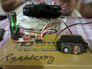
Next we soldered four channel cables with our DevBoard and by attaching each cable with a servo motor ( while attaching another to a power supply) we checked whether our transmitter was working as we programmed or not. The four channels (Throttle, Aileron, Rudder and Elevator) were working just fine.

//
// For classic UDB boards:
// Use a single PPM input connection from the RC receiver to the UDB on RC input channel 4.
// This frees up RC inputs 3, 2, and 1 to act as RC outputs 4, 5, and 6.
// If PPM_ALT_OUTPUT_PINS is set to 0, the 9 available RC outputs will be sent to the
// following pins, in this order: Out1, Out2, Out3, In3, In2, In1, RE0, RE2, RE4.
// With it set to 1, the RC outputs will be in this alternate configuration:
// Out1, Out2, Out3, RE0, RE2, RE4, In3, In2, In1.
//
// For UDB4 boards:
// Use a single PPM input connection from the RC receiver to the UDB on RC input channel 1.
// The 8 standard output channels remain unaffected. 2 additional output channels are available
// on pins RA4 and RA1.
//
// For all boards:
// If you're not sure, leave USE_PPM_INPUT set to 0.
// PPM_NUMBER_OF_CHANNELS is the number of channels sent on the PWM signal. This is
// often different from the NUM_INPUTS value below, and should usually be left at 8.
//
#define USE_PPM_INPUT 0
#define PPM_NUMBER_OF_CHANNELS 8
#define PPM_SIGNAL_INVERTED 0
#define PPM_ALT_OUTPUT_PINS 0
// NUM_INPUTS:
// For classic boards: Set to 1-5 (or 1-8 when using PPM input)
// 1-4 enables only the first 1-4 of the 4 standard input channels
// 5 also enables E8 as the 5th input channel
// For UDB4 boards: Set to 1-8
#define NUM_INPUTS 6
// Channel numbers for each input.
// Use as is, or edit to match your setup.
// - If you're set up to use Rudder Navigation (like MatrixNav), then you may want to swap
// the aileron and rudder channels so that rudder is CHANNEL_1, and aileron is 5.
#define THROTTLE_INPUT_CHANNEL CHANNEL_1
#define AILERON_INPUT_CHANNEL CHANNEL_2
#define ELEVATOR_INPUT_CHANNEL CHANNEL_3
#define RUDDER_INPUT_CHANNEL CHANNEL_4
#define MODE_SWITCH_INPUT_CHANNEL CHANNEL_6
#define CAMERA_PITCH_INPUT_CHANNEL CHANNEL_UNUSED
#define CAMERA_YAW_INPUT_CHANNEL CHANNEL_UNUSED
#define CAMERA_MODE_INPUT_CHANNEL CHANNEL_UNUSED
#define OSD_MODE_SWITCH_INPUT_CHANNEL CHANNEL_UNUSED
#define PASSTHROUGH_A_INPUT_CHANNEL CHANNEL_5
#define PASSTHROUGH_B_INPUT_CHANNEL CHANNEL_UNUSED
#define PASSTHROUGH_C_INPUT_CHANNEL CHANNEL_UNUSED
#define PASSTHROUGH_D_INPUT_CHANNEL CHANNEL_UNUSED
// NUM_OUTPUTS:
// For classic boards: Set to 3, 4, 5, or 6
// 3 enables only the standard 3 output channels
// 4 also enables E0 as the 4th output channel
// 5 also enables E2 as the 5th output channel
// 6 also enables E4 as the 6th output channel
// NOTE: If USE_PPM_INPUT is enabled above, up to 9 outputs are available.)
// For UDB4 boards: Set to 3-8 (or up to 10 using pins RA4 and RA1.)
#define NUM_OUTPUTS 5
// Channel numbers for each output
// Use as is, or edit to match your setup.
// - Only assign each channel to one output purpose
// - If you don't want to use an output channel, set it to CHANNEL_UNUSED
// - If you're set up to use Rudder Navigation (like MatrixNav), then you may want to swap
// the aileron and runner channels so that rudder is CHANNEL_1, and aileron is 5.
//
// NOTE: If your board is powered from your ESC through the throttle cable, make sure to
// connect THROTTLE_OUTPUT_CHANNEL to one of the built-in Outputs (1, 2, or 3) to make
// sure your board gets power.
//
#define THROTTLE_OUTPUT_CHANNEL CHANNEL_1
#define AILERON_OUTPUT_CHANNEL CHANNEL_2
#define ELEVATOR_OUTPUT_CHANNEL CHANNEL_3
#define RUDDER_OUTPUT_CHANNEL CHANNEL_5
#define AILERON_SECONDARY_OUTPUT_CHANNEL CHANNEL_UNUSED
#define CAMERA_PITCH_OUTPUT_CHANNEL CHANNEL_UNUSED
#define CAMERA_YAW_OUTPUT_CHANNEL CHANNEL_UNUSED
#define TRIGGER_OUTPUT_CHANNEL CHANNEL_UNUSED
#define PASSTHROUGH_A_OUTPUT_CHANNEL CHANNEL_4
#define PASSTHROUGH_B_OUTPUT_CHANNEL CHANNEL_UNUSED
#define PASSTHROUGH_C_OUTPUT_CHANNEL CHANNEL_UNUSED
#define PASSTHROUGH_D_OUTPUT_CHANNEL CHANNEL_UNUSED
Next we soldered four channel cables with our DevBoard and by attaching each cable with a servo motor ( while attaching another to a power supply) we checked whether our transmitter was working as we programmed or not. The four channels (Throttle, Aileron, Rudder and Elevator) were working just fine.


Thursday, May 9, 2013
18. More additions to our UDB4 Dev Board
Below is our Dev Board with 3DR G.P.S. MTK V2.0:

Here in the picture below we have added/soldered 7 female (can be seen on the left side of the board) burst pins so that our receiver can be directly connected to the board of our Auto-Pilot (nearly burned my fingers while soldering the burst pins on the board!!! lols!):

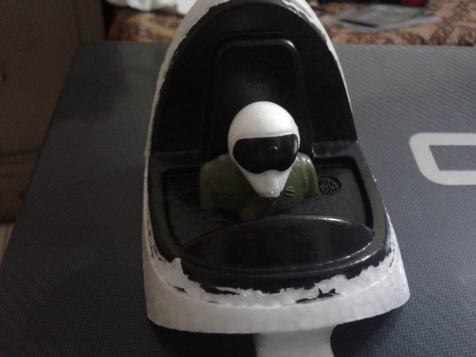
The following changes we are making in the head of the fuselage, in order to place our whole Auto-Pilot with G.P.S.Setup in here:


Monday, May 6, 2013
17. UDB4 DevBoard arrived - New Features n Additions
Our UDB4 Devboard arrived today. It has the following features:
- Compatible with 20-channel EM-406A SiRF III GPS
- Compatible with 50-channel GS407 Helical GPS
- DSPIC33FJ256 Controller (with onboard 3.3V and 5V glue logic)
- DSPIC runs at 120MHz with 8MHz resonator and PLL
- MMA7361 three axis accelerometer
- IDG500 dual axis gyro and ISZ500 single axis gyro
- External 256Kbit EEPROM
- Up to 8 Input, 8 output PWM points
- 6-wire debug header or ICSP header
- 4 separate colored status LEDs
- On board 3.3V and 5V regulators (150mA max)
- Spare USART connection for debugging, flight logging, wireless telemetry, etc.
- 30 spare analog and digital I/O pins for debugging and interfacing to sensors
We added a slot (covering UART RX2, TX2 and GND) to transmit our data for telemetry and another for programming the micro-controller through PIC-Kit 2. You can install the version of PIC-Kit 2 (2.61) and replace a file in it if you already have one and do not wish to use PIC_Kit 3. You may find the necessary software and other stuff for this purpose at the google devboard discussion forum - Software and Replacement File.

For providing power supply to the UDB4 DevBoard we will use our previously made supplier (9 Volt Adapter and 7805 voltage regulator along with 100 micro-farad capacitor).
For UD4 DevBoard we will open MatrixPilot-udb4 program in MPLab IDE software. One of the majore differences here is that the serial output format is defined as: #define SERIAL_OUTPUT_FORMAT SERIAL_MAVLINK and the type of board is defined as: #define BOARD_TYPE UDB4_BOARD.
Saturday, May 4, 2013
16. Auto Take-Off and Auto-Landing programming of the #UAV
For our Auto Take-Off and Auto-Landing - We went in the waypoints.h file of Matrix-Pilot (in MPLab IDE) and entered the following waypoints:

const struct waypointDef waypoints[] = {
{ { 0, 0, 500 } , F_LOITER, CAM_VIEW_LAUNCH },
{ { 8000, 0, 500 } , F_NORMAL, CAM_VIEW_LAUNCH } , // return to, and loiter 75 meters above the start-up position
{ { 5000, 0, 300 } , F_NORMAL, CAM_VIEW_LAUNCH } ,
{ { 2000, 0, 150 } , F_LAND, CAM_VIEW_LAUNCH } ,
{ { 1000, 0, 50 } , F_LAND, CAM_VIEW_LAUNCH } ,
{ { -3000, 0, 10 } , F_LAND, CAM_VIEW_LAUNCH } ,
} ;
Here F_LOITER (Post 6. How are we going to build a more stable Loiter program?) initiates the Auto-Pilot code for its respective waypoint.
const struct waypointDef waypoints[] = {
{ { 8000, 0, 500 } , F_TAKEOFF, CAM_VIEW_LAUNCH } , // return to, and loiter 75 meters above the start-up position
{ { 5000, 0, 300 } , F_NORMAL, CAM_VIEW_LAUNCH } ,
{ { 2000, 0, 150 } , F_LAND, CAM_VIEW_LAUNCH } ,
{ { 1000, 0, 50 } , F_LAND, CAM_VIEW_LAUNCH } ,
{ { -3000, 0, 10 } , F_LAND, CAM_VIEW_LAUNCH } ,
} ;
Here F_TAKEOFF initiates the takeoff (i.e quickly gain the altitude and the waypoint) code for its respective waypoint and F_LAND initiates the Landing Code (in this the throttle turns off at the waypoint prior to its own).
To switch fom Loiter waypoint/mode to next waypoint:
Since the whole Auto-Pilot mode works on one waypoint only, hence to switch out from it we only need to move to the next waypoint. We opened the telemetry.c file (which controls the transmitting and receiving of serial data) and entered a new character 'N' in the following function. On sending 'N' from Happy Kill-more G.C.S to the micro-controller, our program (and in turn our U.A.V.) will switch to the next waypoint with the help of next_waypoint function.
All the above editions are shown below:
void udb_serial_callback_received_byte(uint8_t rxchar) // An interrupt, for serial data, being called in the seriall0_udb.c file
{
(* sio_parse) ( rxchar ) ; // parse the input byte i.e. address of character in function void sio_newMsg() will be loaded in this
return ;
}
void sio_newMsg( uint8_t inchar )
{
if ( inchar == 'V' )
{
sio_parse = &sio_voltage_high ;
}
else if ( inchar == 'N' )
{ next_waypoint();
}
#if ( FLIGHT_PLAN_TYPE == FP_LOGO )
else if ( inchar == 'L' )
#else
else if ( inchar == 'W' )
#endif

After this we entered the following waypoints to join/club both Auto-Pilot and Auto Take-Off & Landing Programs:
{ { 0, 0, 500 } , F_LOITER, CAM_VIEW_LAUNCH },
{ { 8000, 0, 500 } , F_NORMAL, CAM_VIEW_LAUNCH } , // return to, and loiter 75 meters above the start-up position
{ { 5000, 0, 300 } , F_NORMAL, CAM_VIEW_LAUNCH } ,
{ { 2000, 0, 150 } , F_LAND, CAM_VIEW_LAUNCH } ,
{ { 1000, 0, 50 } , F_LAND, CAM_VIEW_LAUNCH } ,
{ { -3000, 0, 10 } , F_LAND, CAM_VIEW_LAUNCH } ,
} ;
Here F_LOITER (Post 6. How are we going to build a more stable Loiter program?) initiates the Auto-Pilot code for its respective waypoint.
Friday, May 3, 2013
15. What's the next program in #UAV designing?
We are planning for a auto take-off and auto-landing. While Auto take-off won't be such a problem, auto landing will be since we have to ensure enough amount of battery for landing and control the gyros and the throttle very specifically so that our U.A.V. might not crash.
Subscribe to:
Posts (Atom)