We went into the options.h file of Matrix-Pilot UDB4 and did the following changes:
(Where left columns is from the receiver and the right column on the devboard)
// Configure Input and Output Channels
//
// For classic UDB boards:
// Use a single PPM input connection from the RC receiver to the UDB on RC input channel 4.
// This frees up RC inputs 3, 2, and 1 to act as RC outputs 4, 5, and 6.
// If PPM_ALT_OUTPUT_PINS is set to 0, the 9 available RC outputs will be sent to the
// following pins, in this order: Out1, Out2, Out3, In3, In2, In1, RE0, RE2, RE4.
// With it set to 1, the RC outputs will be in this alternate configuration:
// Out1, Out2, Out3, RE0, RE2, RE4, In3, In2, In1.
//
// For UDB4 boards:
// Use a single PPM input connection from the RC receiver to the UDB on RC input channel 1.
// The 8 standard output channels remain unaffected. 2 additional output channels are available
// on pins RA4 and RA1.
//
// For all boards:
// If you're not sure, leave USE_PPM_INPUT set to 0.
// PPM_NUMBER_OF_CHANNELS is the number of channels sent on the PWM signal. This is
// often different from the NUM_INPUTS value below, and should usually be left at 8.
//
#define USE_PPM_INPUT 0
#define PPM_NUMBER_OF_CHANNELS 8
#define PPM_SIGNAL_INVERTED 0
#define PPM_ALT_OUTPUT_PINS 0
// NUM_INPUTS:
// For classic boards: Set to 1-5 (or 1-8 when using PPM input)
// 1-4 enables only the first 1-4 of the 4 standard input channels
// 5 also enables E8 as the 5th input channel
// For UDB4 boards: Set to 1-8
#define NUM_INPUTS 6
// Channel numbers for each input.
// Use as is, or edit to match your setup.
// - If you're set up to use Rudder Navigation (like MatrixNav), then you may want to swap
// the aileron and rudder channels so that rudder is CHANNEL_1, and aileron is 5.
#define THROTTLE_INPUT_CHANNEL CHANNEL_1
#define AILERON_INPUT_CHANNEL CHANNEL_2
#define ELEVATOR_INPUT_CHANNEL CHANNEL_3
#define RUDDER_INPUT_CHANNEL CHANNEL_4
#define MODE_SWITCH_INPUT_CHANNEL CHANNEL_6
#define CAMERA_PITCH_INPUT_CHANNEL CHANNEL_UNUSED
#define CAMERA_YAW_INPUT_CHANNEL CHANNEL_UNUSED
#define CAMERA_MODE_INPUT_CHANNEL CHANNEL_UNUSED
#define OSD_MODE_SWITCH_INPUT_CHANNEL CHANNEL_UNUSED
#define PASSTHROUGH_A_INPUT_CHANNEL CHANNEL_5
#define PASSTHROUGH_B_INPUT_CHANNEL CHANNEL_UNUSED
#define PASSTHROUGH_C_INPUT_CHANNEL CHANNEL_UNUSED
#define PASSTHROUGH_D_INPUT_CHANNEL CHANNEL_UNUSED
// NUM_OUTPUTS:
// For classic boards: Set to 3, 4, 5, or 6
// 3 enables only the standard 3 output channels
// 4 also enables E0 as the 4th output channel
// 5 also enables E2 as the 5th output channel
// 6 also enables E4 as the 6th output channel
// NOTE: If USE_PPM_INPUT is enabled above, up to 9 outputs are available.)
// For UDB4 boards: Set to 3-8 (or up to 10 using pins RA4 and RA1.)
#define NUM_OUTPUTS 5
// Channel numbers for each output
// Use as is, or edit to match your setup.
// - Only assign each channel to one output purpose
// - If you don't want to use an output channel, set it to CHANNEL_UNUSED
// - If you're set up to use Rudder Navigation (like MatrixNav), then you may want to swap
// the aileron and runner channels so that rudder is CHANNEL_1, and aileron is 5.
//
// NOTE: If your board is powered from your ESC through the throttle cable, make sure to
// connect THROTTLE_OUTPUT_CHANNEL to one of the built-in Outputs (1, 2, or 3) to make
// sure your board gets power.
//
#define THROTTLE_OUTPUT_CHANNEL CHANNEL_1
#define AILERON_OUTPUT_CHANNEL CHANNEL_2
#define ELEVATOR_OUTPUT_CHANNEL CHANNEL_3
#define RUDDER_OUTPUT_CHANNEL CHANNEL_5
#define AILERON_SECONDARY_OUTPUT_CHANNEL CHANNEL_UNUSED
#define CAMERA_PITCH_OUTPUT_CHANNEL CHANNEL_UNUSED
#define CAMERA_YAW_OUTPUT_CHANNEL CHANNEL_UNUSED
#define TRIGGER_OUTPUT_CHANNEL CHANNEL_UNUSED
#define PASSTHROUGH_A_OUTPUT_CHANNEL CHANNEL_4
#define PASSTHROUGH_B_OUTPUT_CHANNEL CHANNEL_UNUSED
#define PASSTHROUGH_C_OUTPUT_CHANNEL CHANNEL_UNUSED
#define PASSTHROUGH_D_OUTPUT_CHANNEL CHANNEL_UNUSED
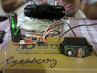
Next we soldered four channel cables with our DevBoard and by attaching each cable with a servo motor ( while attaching another to a power supply) we checked whether our transmitter was working as we programmed or not. The four channels (Throttle, Aileron, Rudder and Elevator) were working just fine.

//
// For classic UDB boards:
// Use a single PPM input connection from the RC receiver to the UDB on RC input channel 4.
// This frees up RC inputs 3, 2, and 1 to act as RC outputs 4, 5, and 6.
// If PPM_ALT_OUTPUT_PINS is set to 0, the 9 available RC outputs will be sent to the
// following pins, in this order: Out1, Out2, Out3, In3, In2, In1, RE0, RE2, RE4.
// With it set to 1, the RC outputs will be in this alternate configuration:
// Out1, Out2, Out3, RE0, RE2, RE4, In3, In2, In1.
//
// For UDB4 boards:
// Use a single PPM input connection from the RC receiver to the UDB on RC input channel 1.
// The 8 standard output channels remain unaffected. 2 additional output channels are available
// on pins RA4 and RA1.
//
// For all boards:
// If you're not sure, leave USE_PPM_INPUT set to 0.
// PPM_NUMBER_OF_CHANNELS is the number of channels sent on the PWM signal. This is
// often different from the NUM_INPUTS value below, and should usually be left at 8.
//
#define USE_PPM_INPUT 0
#define PPM_NUMBER_OF_CHANNELS 8
#define PPM_SIGNAL_INVERTED 0
#define PPM_ALT_OUTPUT_PINS 0
// NUM_INPUTS:
// For classic boards: Set to 1-5 (or 1-8 when using PPM input)
// 1-4 enables only the first 1-4 of the 4 standard input channels
// 5 also enables E8 as the 5th input channel
// For UDB4 boards: Set to 1-8
#define NUM_INPUTS 6
// Channel numbers for each input.
// Use as is, or edit to match your setup.
// - If you're set up to use Rudder Navigation (like MatrixNav), then you may want to swap
// the aileron and rudder channels so that rudder is CHANNEL_1, and aileron is 5.
#define THROTTLE_INPUT_CHANNEL CHANNEL_1
#define AILERON_INPUT_CHANNEL CHANNEL_2
#define ELEVATOR_INPUT_CHANNEL CHANNEL_3
#define RUDDER_INPUT_CHANNEL CHANNEL_4
#define MODE_SWITCH_INPUT_CHANNEL CHANNEL_6
#define CAMERA_PITCH_INPUT_CHANNEL CHANNEL_UNUSED
#define CAMERA_YAW_INPUT_CHANNEL CHANNEL_UNUSED
#define CAMERA_MODE_INPUT_CHANNEL CHANNEL_UNUSED
#define OSD_MODE_SWITCH_INPUT_CHANNEL CHANNEL_UNUSED
#define PASSTHROUGH_A_INPUT_CHANNEL CHANNEL_5
#define PASSTHROUGH_B_INPUT_CHANNEL CHANNEL_UNUSED
#define PASSTHROUGH_C_INPUT_CHANNEL CHANNEL_UNUSED
#define PASSTHROUGH_D_INPUT_CHANNEL CHANNEL_UNUSED
// NUM_OUTPUTS:
// For classic boards: Set to 3, 4, 5, or 6
// 3 enables only the standard 3 output channels
// 4 also enables E0 as the 4th output channel
// 5 also enables E2 as the 5th output channel
// 6 also enables E4 as the 6th output channel
// NOTE: If USE_PPM_INPUT is enabled above, up to 9 outputs are available.)
// For UDB4 boards: Set to 3-8 (or up to 10 using pins RA4 and RA1.)
#define NUM_OUTPUTS 5
// Channel numbers for each output
// Use as is, or edit to match your setup.
// - Only assign each channel to one output purpose
// - If you don't want to use an output channel, set it to CHANNEL_UNUSED
// - If you're set up to use Rudder Navigation (like MatrixNav), then you may want to swap
// the aileron and runner channels so that rudder is CHANNEL_1, and aileron is 5.
//
// NOTE: If your board is powered from your ESC through the throttle cable, make sure to
// connect THROTTLE_OUTPUT_CHANNEL to one of the built-in Outputs (1, 2, or 3) to make
// sure your board gets power.
//
#define THROTTLE_OUTPUT_CHANNEL CHANNEL_1
#define AILERON_OUTPUT_CHANNEL CHANNEL_2
#define ELEVATOR_OUTPUT_CHANNEL CHANNEL_3
#define RUDDER_OUTPUT_CHANNEL CHANNEL_5
#define AILERON_SECONDARY_OUTPUT_CHANNEL CHANNEL_UNUSED
#define CAMERA_PITCH_OUTPUT_CHANNEL CHANNEL_UNUSED
#define CAMERA_YAW_OUTPUT_CHANNEL CHANNEL_UNUSED
#define TRIGGER_OUTPUT_CHANNEL CHANNEL_UNUSED
#define PASSTHROUGH_A_OUTPUT_CHANNEL CHANNEL_4
#define PASSTHROUGH_B_OUTPUT_CHANNEL CHANNEL_UNUSED
#define PASSTHROUGH_C_OUTPUT_CHANNEL CHANNEL_UNUSED
#define PASSTHROUGH_D_OUTPUT_CHANNEL CHANNEL_UNUSED
Next we soldered four channel cables with our DevBoard and by attaching each cable with a servo motor ( while attaching another to a power supply) we checked whether our transmitter was working as we programmed or not. The four channels (Throttle, Aileron, Rudder and Elevator) were working just fine.

