Friday, May 31, 2013

31. Further modifications in #Software for Battery Monitoring

We realized that by merely doing the flag int_flightplan 1 in telemetry.c will not direct our program in Return To Land Mode. We discovered in the programming that RTL mode can only be achieved when two conditions are met:
  1. Program/drone is in Auto-Pilot Mode, for this we need our gps to be locked &
  2. failSafePulses or the pulses coming from the transmitter are 0 i.e. we have lost the radio signal
This can be seen from the following program in states.c file:

/////// Come home state, entered when the radio signal is lost, and gps is locked.
void ent_returnS()
{
flags._.GPS_steering = 1 ;
flags._.pitch_feedback = 1 ;
flags._.altitude_hold_throttle = (ALTITUDEHOLD_WAYPOINT == AH_FULL) ;
flags._.altitude_hold_pitch = (ALTITUDEHOLD_WAYPOINT == AH_FULL || ALTITUDEHOLD_WAYPOINT == AH_PITCH_ONLY) ;
#if ( FAILSAFE_TYPE == FAILSAFE_RTL )
init_flightplan( 1 ) ;
#elif ( FAILSAFE_TYPE == FAILSAFE_MAIN_FLIGHTPLAN )
if ( stateS != &waypointS )
{
init_flightplan( 0 ) ; // Only reset non-rtl waypoints if not already following waypoints
}

The condition to control the failSafePulses is mentioned in the background.c file:


if ( ( failSafePulses == 0 ) || ( noisePulses > MAX_NOISE_RATE ) )
{
if (udb_flags._.radio_on == 1) {
udb_flags._.radio_on = 0 ;
udb_callback_radio_did_turn_off() ;
}
LED_GREEN = LED_OFF ;
noisePulses = 0 ; // reset count of noise pulses
}
else
{
udb_flags._.radio_on = 1 ;
LED_GREEN = LED_ON ;
}
failSafePulses = 0 ;
}

Mode is mentioned in telemetry.c file and can be controlled from the receiver:

void serial_output_8hz( void )
{
uint16_t mode ;
struct relative2D matrix_accum ;
union longbbbb accum ;
int16_t desired_dir_deg ;  // desired_dir converted to a bearing (0-360)
int32_t earth_pitch ; // pitch in binary angles ( 0-255 is 360 degreres)
int32_t earth_roll ; // roll of the plane with respect to earth frame
//int32_t earth_yaw ; // yaw with respect to earth frame
accum.WW  = ( desired_dir * BYTECIR_TO_DEGREE ) + 32768 ;
desired_dir_deg  = accum._.W1 - 90 ; // "Convert UAV DevBoad Earth" to Compass Bearing
if ( desired_dir_deg < 0 ) desired_dir_deg += 360 ; 

if (flags._.GPS_steering == 0 && flags._.pitch_feedback == 0)
mode = 1 ;
else if (flags._.GPS_steering == 0 && flags._.pitch_feedback == 1)
mode = 2 ;
else if (flags._.GPS_steering == 1 && flags._.pitch_feedback == 1 && udb_flags._.radio_on == 1)
mode = 3 ;
else if (flags._.GPS_steering == 1 && flags._.pitch_feedback == 1 && udb_flags._.radio_on == 0)
mode = 0 ;
else
mode = 99 ; // Unknown
Hence to meet the above two conditions we created a flag BATT_FLAG which we defined in telemetry.c and declared as extern in defines.h file. When BATT_FLAG is set to 1 (in telemetry.c file) the int_flightplan  will become 0 (in background.c file) and thus enable out RTL Mode.

In telemetry.c file:

#define batt_min_value 16000
int BATT_FLAG =0;

if((udb_analogInputs[0].value<batt_min_value) && (mode = =3)) // if battery value goes below 16000 and is in Auto-Pilot Mode 
{
BATT_FLAG =1;
}
//////////////////////////////////////////////////////

if(mode<3) // if in Manual or Stabilized Mode then will never make BATT_FLAG 1 and int_flightplan 0
{
BATT_FLAG =0;
}

In background.c file:

// check to see if at least one valid pulse has been received,
// and also that the noise rate has not been exceeded
if(BATT_FLAG = =1)
{
failSafePulses =0;
}
if ( ( failSafePulses = = 0 ) || ( noisePulses > MAX_NOISE_RATE ) )
{
if (udb_flags._.radio_on == 1) {
udb_flags._.radio_on = 0 ;
udb_callback_radio_did_turn_off() ;
}
LED_GREEN = LED_OFF ;
noisePulses = 0 ; // reset count of noise pulses
}
else
{
udb_flags._.radio_on = 1 ;
LED_GREEN = LED_ON ;
}
failSafePulses = 0 ;
}

Here if we change from Auto-Pilot Mode to any other Mode then our BATT_FLAG will become 0 and our failSafePulses will start receiving real time signals from the transmitter on the drone.

How we monitored our changes, I will mention that in my next post.

30. Pictures - Voltage Divider Circuit for Battery Monitoring Circuit for #Unmanned AV #UAV


Thursday, May 30, 2013

29. Battery Monitoring Circuit for #UAV - #Software

Now we are working to create a program where we will guide our aircraft in case of insufficient battery. For this purpose we have added a voltage divider circuit, using 1k (R1) and .33k (R2) ohm resistances, to our existing UDB4 board and made the following changes in the telemetry.c file: 

#define batt_min_value 88

///////////////////////// battery health testing code
if(udb_analogInputs[0].value<batt_min_value)
{
init_flightplan( 1 );
}
//////////////////////////////////////////////////////

Here udb_analogInputs[0].value is real-time or current value that comes on one of our Analog pins of PIC controller (from AN15 to AN 18). If it goes below a certain value (for 3S LIPO battery - below 3.6 Volts each or net 10.8 Volts) then the program will switch to Return to Land (RTL) mode. 

In order to read what exact value that will come at full charge i.e. 12.48 Volts on the Analog Pins we replaced our diff in telemetry.c with udb_analogInputs[0].value so that we may set our batt_min_value:

// The Ardupilot GroundStation protocol is mostly documented here:
//    http://diydrones.com/profiles/blogs/ardupilot-telemetry-protocol
///////////////////////// battery health testing code
if(udb_analogInputs[0].value<batt_min_value)
{
init_flightplan( 1 );
}
//////////////////////////////////////////////////////


if (udb_heartbeat_counter % 40 == 0)  // Every 8 runs (5 heartbeat counts per 8Hz)
{
serial_output("!!!LAT:%li,LON:%li,SPD:%.2f,CRT:%.2f,ALT:%li,ALH:%i,CRS:%.2f,BER:%i,WPN:%i,DST:%i,BTV:%.2f***\r\n"
 "+++THH:%i,RLL:%li,PCH:%li,STT:%i,***\r\n",
lat_gps.WW / 10 , long_gps.WW / 10 , (float)(sog_gps.BB / 100.0), (float)(climb_gps.BB / 100.0),
(alt_sl_gps.WW - alt_origin.WW) / 100, desiredHeight, (float)(cog_gps.BB / 100.0), desired_dir_deg,
waypointIndex, udb_analogInputs[0].value, (float)(voltage_milis.BB / 100.0), 
(int16_t)((udb_pwOut[THROTTLE_OUTPUT_CHANNEL] - udb_pwTrim[THROTTLE_OUTPUT_CHANNEL])/20),
earth_roll, earth_pitch,
mode
) ;
}

We will be able to monitor it on Happy Killmore GCS software as we did our diff variable earlier (Switch-out from Auto-Pilot Mode : Another function for #UAV)

Also, if init_flightplan( 1 ); is set to one as here, then we will be able to switch to RTL mode or else not as we can see in the flightplan-waypoints.c file:

// In the future, we could include more than 2 waypoint sets...
// flightplanNum is 0 for main waypoints, and 1 for RTL waypoints
void init_flightplan ( int16_t flightplanNum )
{
if ( flightplanNum == 1 ) // RTL waypoint set
{
currentWaypointSet = (struct waypointDef*)rtlWaypoints ;
numPointsInCurrentSet = NUMBER_RTL_POINTS ;
}
else if ( flightplanNum == 0 ) // Main waypoint set
{
currentWaypointSet = (struct waypointDef*)waypoints ;
    numPointsInCurrentSet = NUMBER_POINTS ;
    }

Wednesday, May 29, 2013

28. #Funny , #Hilarious n #Awkward

That awkward moment when in the middle of night (ripe time for a typical engineer to work) you are all set with your PCB, components - resistors, capacitors n controllers etc ..., the soldering rod to make your circuit, when suddenly you realize that you do not have soldering wire!!! Aww man!!!

Wednesday, May 22, 2013

26. Pictures - #Funny - #Ailerons going out of function for a while

As I had posted previously, we had to remove one of the servos of the drone. Reason being that in Auto-Pilot mode it was skipping a step. This was as shown earlier it had a broken step or tooth. We tried to repair that servo motor (like by exchanging its gear set with another ones, that was a metal one) but it could not be possible. Therefore we have decided to order a new one. 

But then we thought that how are we going to test our program in real time environment? For this purpose we have removed the other aileron's motor too and fixed both of them for a while.

So now we had to extend the rudder so that it may take on the role of ailerons too. Well this is funny, but it will work n its innovation at its best. This is how we did it:


Monday, May 20, 2013

25. Had to remove the servo of one of the Ailerons


24. Update Switch-out from Auto-Pilot Mode

1. In order to receive indication physically on Dev Board that we have switched out from Auto-Pilot Mode  we use the Blue LED (declared in ConfigUDB4.h file) present on it.

So in servoMix.c file we made the following changes:

void startupfuntion(void)
{
if (startflag == 0)
{
startflag =1;
currentvalue = mychannelvalue;
}
}

void checkmode(void)
{
diff = mychannelvalue-currentvalue;
if((diff>100) || (diff<-100))
//if (diff==1)
{
currentvalue = mychannelvalue;
if(LED_BLUE == 0)
LED_BLUE = 1;
else
LED_BLUE = 0;
if (flags._.GPS_steering == 1 && flags._.pitch_feedback == 1 && udb_flags._.radio_on == 1)
            {
 next_waypoint();
              currentvalue = mychannelvalue;
}
}
}

2. Also we declared our int variable - diff in defines.h file so that it may be used for other purposes too, and removed its static declaration:

extern int diff; //extern helps to access a variable/function defined in a single file and makes it available for all the other files in our program

3. In order to check what difference in servoMix.c file (diff) is coming in the - diff = mychannelvalue-currentvalue;, so that we may check whether vale in our condition - if((diff>100) || (diff<-100)) is within range or not. So we opened telemetry.c file and did the following changes:


// Yaw
// Earth Frame of Reference
// Ardustation does not use yaw in degrees
// matrix_accum.x = rmat[4] ;
// matrix_accum.y = rmat[1] ;
// earth_yaw = rect_to_polar(&matrix_accum) ; // binary angle (0 - 256 = 360 degrees)
// earth_yaw = (earth_yaw * BYTECIR_TO_DEGREE) >> 16 ; // switch polarity, convert to -180 - 180 degrees
// The Ardupilot GroundStation protocol is mostly documented here:
//    http://diydrones.com/profiles/blogs/ardupilot-telemetry-protocol
if (udb_heartbeat_counter % 40 == 0)  // Every 8 runs (5 heartbeat counts per 8Hz)
{
serial_output("!!!LAT:%li,LON:%li,SPD:%.2f,CRT:%.2f,ALT:%li,ALH:%i,CRS:%.2f,BER:%i,WPN:%i,DST:%i,BTV:%.2f***\r\n"
 "+++THH:%i,RLL:%li,PCH:%li,STT:%i,***\r\n",
lat_gps.WW / 10 , long_gps.WW / 10 , (float)(sog_gps.BB / 100.0), (float)(climb_gps.BB / 100.0),
(alt_sl_gps.WW - alt_origin.WW) / 100, desiredHeight, (float)(cog_gps.BB / 100.0), desired_dir_deg,
waypointIndex, diff, (float)(voltage_milis.BB / 100.0), 
(int16_t)((udb_pwOut[THROTTLE_OUTPUT_CHANNEL] - udb_pwTrim[THROTTLE_OUTPUT_CHANNEL])/20),
earth_roll, earth_pitch,
mode
) ;
}
else if (udb_heartbeat_counter % 10 == 0)  // Every 2 runs (5 heartbeat counts per 8Hz)
{
serial_output("+++THH:%i,RLL:%li,PCH:%li,STT:%i,***\r\n",
(int16_t)((udb_pwOut[THROTTLE_OUTPUT_CHANNEL] - udb_pwTrim[THROTTLE_OUTPUT_CHANNEL])/20),
earth_roll, earth_pitch,
mode
) ;
}
return ;
}

We changed to diff from tofinish_line so that in Realterm Software we may see the diff value coming and set our condition accordingly.


4. And finally: What is the meaning of diff?

Diff is the decimal difference in milliseconds that comes between the up and down position of the switch we will use, on the transmitter, to switch-out from Auto-Pilot mode.

Saturday, May 18, 2013

23. Switch-out from Auto-Pilot Mode : Another function for #UAV

In our previous programming segment (16. Auto Take-Off and Auto-Landing programming of the #UAV and 6. How are we going to build a more stable Loiter program? - The Idea.) we had made Auto-Pilot program and also an Auto-take off and Auto-landing program for our U.A.V.

Then we thought more. What if due to some reason we want our U.A.V to move out of the Auto-Pilot mode towards the next desired waypoint (like sometimes we may want a quick auto-landing or surveillance of some other area)?. Hence we came up with another addition to the whole program we had made so far.

We decided to use one of the 2 output channels left (rest 5 out total 7 are used for Aileron, Throttle, rudder, Elevator and Mode) of the UDB Devboard to receive a signal from our transmitter so that whenever we change the position of the switch from its initial position (at start-up) i.e. from up to down or down to up, our  DevBoard will switch out of the Auto-Pilot mode.

So in order form a logic, we first tried a simple C program in which if we press any letter different from the one we have put in the memory (through scanf function), then it will display a certain message and if we press the same letter as in the memory then another certain message will appear:


#include <stdio.h>
#include <conio.h>

int main()

{
char in, oc;
in = 'j';
printf("Testing code");
while(1)
{
          printf("input pls");
          oc=getch(); // so that we do not have to press enter every-time we enter something on screen
          //scanf("%c", &oc);
          //printf("yes wrkin");
          if (oc!=in)
             {
                     printf("Matched");
                    if ( (oc == 'j')||(oc == 'h'))
                       {
                                printf("moved to next waypoint");
                                in = oc;
                       }
             }
}
   getch();
   return 0;
}

To implement this idea we went into the servoMix.c file of our program and edited the following:

static int mychannelvalue =0;
static char startflag =0; // will be used to check position of switch at sart-up only once
void startupfuntion(void); //to store the current position of the switch
void checkmode (void); // to check the position of the switch, if changed then switch-out of Auto-Pilot mode
static int currentvalue =0;

// Helicopter airframe
// Mix half of roll_control and half of pitch_control into aileron channels
// Mix full pitch_control into elevator
// Ignore waggle for now
#if ( AIRFRAME_TYPE == AIRFRAME_HELI )
temp = pwManual[AILERON_INPUT_CHANNEL] +
REVERSE_IF_NEEDED(AILERON_CHANNEL_REVERSED, roll_control/2 +

pitch_control/2) ;
udb_pwOut[AILERON_OUTPUT_CHANNEL] = udb_servo_pulsesat( temp ) ;

temp = pwManual[ELEVATOR_INPUT_CHANNEL] +

REVERSE_IF_NEEDED(ELEVATOR_CHANNEL_REVERSED, pitch_control) ;
udb_pwOut[ELEVATOR_OUTPUT_CHANNEL] = udb_servo_pulsesat( temp ) ;

temp = pwManual[AILERON_SECONDARY_OUTPUT_CHANNEL] +
REVERSE_IF_NEEDED(AILERON_SECONDARY_CHANNEL_REVERSED,

-roll_control/2 + pitch_control/2) ;
udb_pwOut[AILERON_SECONDARY_OUTPUT_CHANNEL] = temp ;

temp = pwManual[RUDDER_INPUT_CHANNEL] /*+

REVERSE_IF_NEEDED(RUDDER_CHANNEL_REVERSED, yaw_control)*/ ;
udb_pwOut[RUDDER_OUTPUT_CHANNEL] = udb_servo_pulsesat( temp ) ;

if ( pwManual[THROTTLE_INPUT_CHANNEL] == 0 )
{
udb_pwOut[THROTTLE_OUTPUT_CHANNEL] = 0 ;
}
else
{
temp = pwManual[THROTTLE_INPUT_CHANNEL] +

REVERSE_IF_NEEDED(THROTTLE_CHANNEL_REVERSED, throttle_control) ;
udb_pwOut[THROTTLE_OUTPUT_CHANNEL] = udb_servo_pulsesat( temp ) ;
}
#endif
mychannelvalue = udb_servo_pulsesat( pwManual[PASSTHROUGH_A_INPUT_CHANNEL] )

;

startupfuntion();
checkmode();
// next_waypoint();      

udb_pwOut[PASSTHROUGH_A_OUTPUT_CHANNEL] = udb_servo_pulsesat(

pwManual[PASSTHROUGH_A_INPUT_CHANNEL] ) ;
udb_pwOut[PASSTHROUGH_B_OUTPUT_CHANNEL] = udb_servo_pulsesat(

pwManual[PASSTHROUGH_B_INPUT_CHANNEL] ) ;
udb_pwOut[PASSTHROUGH_C_OUTPUT_CHANNEL] = udb_servo_pulsesat(

pwManual[PASSTHROUGH_C_INPUT_CHANNEL] ) ;
udb_pwOut[PASSTHROUGH_D_OUTPUT_CHANNEL] = udb_servo_pulsesat(

pwManual[PASSTHROUGH_D_INPUT_CHANNEL] ) ;
}

void cameraServoMix( void )
{
int32_t temp ;
int16_t pwManual[NUM_INPUTS+1] ;

// If radio is off, use udb_pwTrim values instead of the udb_pwIn values
for (temp = 0; temp <= NUM_INPUTS; temp++)
if (udb_flags._.radio_on)
pwManual[temp] = udb_pwIn[temp];
else
pwManual[temp] = udb_pwTrim[temp];

temp = ( pwManual[CAMERA_PITCH_INPUT_CHANNEL] - 3000 ) +

REVERSE_IF_NEEDED(CAMERA_PITCH_CHANNEL_REVERSED,
cam_pitch_servo_pwm_delta ) ;
temp = cam_pitchServoLimit(temp) ;
udb_pwOut[CAMERA_PITCH_OUTPUT_CHANNEL] = udb_servo_pulsesat( temp + 3000 ) ;

temp = ( pwManual[CAMERA_YAW_INPUT_CHANNEL] - 3000 ) +

REVERSE_IF_NEEDED(CAMERA_YAW_CHANNEL_REVERSED,
cam_yaw_servo_pwm_delta ) ;
temp = cam_yawServoLimit(temp) ;
udb_pwOut[CAMERA_YAW_OUTPUT_CHANNEL] = udb_servo_pulsesat( temp + 3000 ) ;
}

void startupfuntion(void)
{
if (startflag == 0)
{
startflag =1;
currentvalue = mychannelvalue;
}
}

void checkmode(void)
{
int diff;
diff = mychannelvalue-currentvalue;
 if(diff>100 || diff<-100)
{
             if (flags._.GPS_steering == 1 && flags._.pitch_feedback == 1 && udb_flags._.radio_on == 1) //to check if in Auto-Pilot mode, else will never go for the function, make sure only Auto-Pilot switch-out
            {
 next_waypoint();
                           currentvalue = mychannelvalue;
}
}
}

22. Tip2 for #UAV

Always debug (i.e. check for values in a particular part of the program) your program in a PIC controller testing kit with MPLab 8.9, because UDB4 Devboard does not provide the facility to debug, i.e it can't be debugged with PICKit 2. This will help you as you will discover in the next post on this blog. (Wink! Wink!)
  1. You may double click on the left hand side of the line where you want to debug. A letter 'B' in red circle will appear at that point. Change the mode of the MPLab setup to Debug (originally its Release). 
  2. After the changes above you may build your program.
  3. Connect the PICKit 2 with the testing board and program it.
  4. Next go to View - Locals. A window will appear which will show you values at the breakpoints set by you every time you Run the debugging.


Wednesday, May 15, 2013

21. Tip1 for #UAV

Tip: After making all the changes to the hardware of the fuselage according to your requirements, do check the Center of Gravity of the whole plane.

Monday, May 13, 2013

19. Coordinating hardware with our program

We went into the options.h file of Matrix-Pilot UDB4 and did the following changes:

(Where left columns is from the receiver and the right column on the devboard)

// Configure Input and Output Channels
//
// For classic UDB boards:
// Use a single PPM input connection from the RC receiver to the UDB on RC input channel 4.
// This frees up RC inputs 3, 2, and 1 to act as RC outputs 4, 5, and 6.
// If PPM_ALT_OUTPUT_PINS is set to 0, the 9 available RC outputs will be sent to the
// following pins, in this order: Out1, Out2, Out3, In3, In2, In1, RE0, RE2, RE4.
// With it set to 1, the RC outputs will be in this alternate configuration:
// Out1, Out2, Out3, RE0, RE2, RE4, In3, In2, In1.
//
// For UDB4 boards:
// Use a single PPM input connection from the RC receiver to the UDB on RC input channel 1.
// The 8 standard output channels remain unaffected.  2 additional output channels are available
// on pins RA4 and RA1.
//
// For all boards:
// If you're not sure, leave USE_PPM_INPUT set to 0.
// PPM_NUMBER_OF_CHANNELS is the number of channels sent on the PWM signal.  This is
// often different from the NUM_INPUTS value below, and should usually be left at 8.
//
#define USE_PPM_INPUT 0
#define PPM_NUMBER_OF_CHANNELS 8
#define PPM_SIGNAL_INVERTED 0
#define PPM_ALT_OUTPUT_PINS 0

// NUM_INPUTS:
// For classic boards: Set to 1-5 (or 1-8 when using PPM input)
//   1-4 enables only the first 1-4 of the 4 standard input channels
//   5 also enables E8 as the 5th input channel
// For UDB4 boards: Set to 1-8
#define NUM_INPUTS 6

// Channel numbers for each input.
// Use as is, or edit to match your setup.
//   - If you're set up to use Rudder Navigation (like MatrixNav), then you may want to swap
//     the aileron and rudder channels so that rudder is CHANNEL_1, and aileron is 5.
#define THROTTLE_INPUT_CHANNEL CHANNEL_1
#define AILERON_INPUT_CHANNEL CHANNEL_2
#define ELEVATOR_INPUT_CHANNEL CHANNEL_3
#define RUDDER_INPUT_CHANNEL CHANNEL_4
#define MODE_SWITCH_INPUT_CHANNEL CHANNEL_6
#define CAMERA_PITCH_INPUT_CHANNEL CHANNEL_UNUSED
#define CAMERA_YAW_INPUT_CHANNEL CHANNEL_UNUSED
#define CAMERA_MODE_INPUT_CHANNEL CHANNEL_UNUSED
#define OSD_MODE_SWITCH_INPUT_CHANNEL        CHANNEL_UNUSED
#define PASSTHROUGH_A_INPUT_CHANNEL CHANNEL_5
#define PASSTHROUGH_B_INPUT_CHANNEL CHANNEL_UNUSED
#define PASSTHROUGH_C_INPUT_CHANNEL CHANNEL_UNUSED
#define PASSTHROUGH_D_INPUT_CHANNEL CHANNEL_UNUSED

// NUM_OUTPUTS:
// For classic boards: Set to 3, 4, 5, or 6
//   3 enables only the standard 3 output channels
//   4 also enables E0 as the 4th output channel
//   5 also enables E2 as the 5th output channel
//   6 also enables E4 as the 6th output channel
//   NOTE: If USE_PPM_INPUT is enabled above, up to 9 outputs are available.)
// For UDB4 boards: Set to 3-8 (or up to 10 using pins RA4 and RA1.)
#define NUM_OUTPUTS 5

// Channel numbers for each output
// Use as is, or edit to match your setup.
//   - Only assign each channel to one output purpose
//   - If you don't want to use an output channel, set it to CHANNEL_UNUSED
//   - If you're set up to use Rudder Navigation (like MatrixNav), then you may want to swap
//     the aileron and runner channels so that rudder is CHANNEL_1, and aileron is 5.
//
// NOTE: If your board is powered from your ESC through the throttle cable, make sure to
// connect THROTTLE_OUTPUT_CHANNEL to one of the built-in Outputs (1, 2, or 3) to make
// sure your board gets power.
//
#define THROTTLE_OUTPUT_CHANNEL CHANNEL_1
#define AILERON_OUTPUT_CHANNEL CHANNEL_2
#define ELEVATOR_OUTPUT_CHANNEL CHANNEL_3
#define RUDDER_OUTPUT_CHANNEL CHANNEL_5
#define AILERON_SECONDARY_OUTPUT_CHANNEL        CHANNEL_UNUSED
#define CAMERA_PITCH_OUTPUT_CHANNEL CHANNEL_UNUSED
#define CAMERA_YAW_OUTPUT_CHANNEL CHANNEL_UNUSED
#define TRIGGER_OUTPUT_CHANNEL CHANNEL_UNUSED
#define PASSTHROUGH_A_OUTPUT_CHANNEL CHANNEL_4
#define PASSTHROUGH_B_OUTPUT_CHANNEL CHANNEL_UNUSED
#define PASSTHROUGH_C_OUTPUT_CHANNEL CHANNEL_UNUSED
#define PASSTHROUGH_D_OUTPUT_CHANNEL CHANNEL_UNUSED

Next we soldered four channel cables with our DevBoard and by attaching each cable with a servo motor  ( while attaching another to a power supply) we checked whether our transmitter was working as we programmed or not. The four channels (Throttle, Aileron, Rudder and Elevator) were working just fine.


Thursday, May 9, 2013

18. More additions to our UDB4 Dev Board

Below is our Dev Board with 3DR G.P.S. MTK V2.0: 


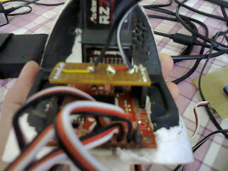
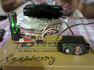
Here in the picture below we have added/soldered 7 female (can be seen on the left side of the board) burst pins so that our receiver can be directly connected to the board of our Auto-Pilot (nearly burned my fingers while soldering the burst pins on the board!!! lols!):


The following changes we are making in the head of the fuselage, in order to place our whole Auto-Pilot with G.P.S.Setup in here:


Monday, May 6, 2013

17. UDB4 DevBoard arrived - New Features n Additions

Our UDB4 Devboard arrived today. It has the following features:
  1. Compatible with 20-channel EM-406A SiRF III GPS
  2. Compatible with 50-channel GS407 Helical GPS
  3. DSPIC33FJ256 Controller (with onboard 3.3V and 5V glue logic)
  4. DSPIC runs at 120MHz with 8MHz resonator and PLL
  5. MMA7361 three axis accelerometer
  6. IDG500 dual axis gyro and ISZ500 single axis gyro
  7. External 256Kbit EEPROM
  8. Up to 8 Input, 8 output PWM points
  9. 6-wire debug header or ICSP header
  10. 4 separate colored status LEDs
  11. On board 3.3V and 5V regulators (150mA max)
  12. Spare USART connection for debugging, flight logging, wireless telemetry, etc.
  13. 30 spare analog and digital I/O pins for debugging and interfacing to sensors
We added a slot (covering UART RX2, TX2 and GND) to transmit our data for telemetry and another for programming the micro-controller through PIC-Kit 2. You can install the version of PIC-Kit 2 (2.61) and replace a file in it if you already have one and do not wish to use PIC_Kit 3. You may find the necessary software and other stuff for this purpose at the google devboard discussion forum - Software and Replacement File.


For providing power supply to the UDB4 DevBoard we will use our previously made supplier (9 Volt Adapter and 7805 voltage regulator along with 100 micro-farad capacitor). 
For UD4 DevBoard we will open MatrixPilot-udb4 program in MPLab IDE software. One of the majore differences here is that the serial output format is defined as: #define SERIAL_OUTPUT_FORMAT SERIAL_MAVLINK and the type of board is defined as: #define BOARD_TYPE UDB4_BOARD.

Saturday, May 4, 2013

16. Auto Take-Off and Auto-Landing programming of the #UAV

For our Auto Take-Off and Auto-Landing - We went in the  waypoints.h file of Matrix-Pilot (in MPLab IDE) and entered the following waypoints:

const struct waypointDef waypoints[] = {
{ {   8000,   0, 500 } , F_TAKEOFF, CAM_VIEW_LAUNCH } ,  // return to, and loiter 75 meters above the start-up position
{ {   5000,   0, 300 } , F_NORMAL, CAM_VIEW_LAUNCH } ,
    { {   2000,   0, 150 } , F_LAND, CAM_VIEW_LAUNCH } ,
{ {   1000,   0, 50 } , F_LAND, CAM_VIEW_LAUNCH } ,
{ {   -3000,   0, 10 } , F_LAND, CAM_VIEW_LAUNCH } ,
} ;

Here F_TAKEOFF initiates the takeoff  (i.e quickly gain the altitude and the waypoint) code for its respective waypoint and F_LAND initiates the Landing Code (in this the throttle turns off at the waypoint prior to its own).

To switch fom Loiter waypoint/mode to next waypoint: 

Since the whole Auto-Pilot mode works on one waypoint only, hence to switch out from it we only need to move to the next waypoint. We opened the telemetry.c file (which controls the transmitting and receiving of serial data) and entered a new character 'N' in the following function. On sending 'N' from Happy Kill-more G.C.S to the micro-controller, our program  (and in turn our U.A.V.) will switch to the next waypoint with the help of next_waypoint function. 

All the above editions are shown below:

void udb_serial_callback_received_byte(uint8_t rxchar) // An interrupt, for serial data, being called in the seriall0_udb.c file
{
(* sio_parse) ( rxchar ) ; // parse the input byte i.e. address of character in function void sio_newMsg() will be loaded in this
return ;
}
void sio_newMsg( uint8_t inchar )
{
if ( inchar == 'V' )
{
sio_parse = &sio_voltage_high ;
}
else if ( inchar == 'N' )
{ next_waypoint();
}
#if ( FLIGHT_PLAN_TYPE == FP_LOGO )
else if ( inchar == 'L' )
#else
else if ( inchar == 'W' )
#endif


After this we entered the following waypoints to join/club both Auto-Pilot and Auto Take-Off & Landing Programs:

const struct waypointDef waypoints[] = {
{ {   0,   0, 500 } , F_LOITER, CAM_VIEW_LAUNCH },
{ {   8000,   0, 500 } , F_NORMAL, CAM_VIEW_LAUNCH } ,  // return to, and loiter 75 meters above the start-up position
{ {   5000,   0, 300 } , F_NORMAL, CAM_VIEW_LAUNCH } ,
    { {   2000,   0, 150 } , F_LAND, CAM_VIEW_LAUNCH } ,
{ {   1000,   0, 50 } , F_LAND, CAM_VIEW_LAUNCH } ,
{ {   -3000,   0, 10 } , F_LAND, CAM_VIEW_LAUNCH } ,
} ;

Here F_LOITER (Post 6. How are we going to build a more stable Loiter program?) initiates the Auto-Pilot code for its respective waypoint.

Friday, May 3, 2013

15. What's the next program in #UAV designing?

We are planning for a auto take-off and auto-landing. While Auto take-off won't be such a problem, auto landing will be since we have to ensure enough amount of battery for landing and control the gyros and the throttle very specifically so that our U.A.V. might not crash.

14. What is MatrixPilot? A Glance.

MatrixPilot is the latest firmware for the UAV Dev Board. It is based on William Premerlani's MatrixNav and AileronAssist firmwares, adds many important and fun new features, and allows much more configurability.

Supported Air Frames:

MatrixPilot can be used to control a wide variety of airframes:
  • Standard Airplane: Stabilize and navigate using elevator, and either ailerons, rudder, or both. This is the Airframe type to use if you're upgrading from AileronAssist or MatrixNav.
  • Delta Wing: Similar to the Standard Airplane, but all control is performed through the 2 "elevon" control surfaces.
  • V-Tail: Similar to the Standard Airplane, but rudder and elevator channels are mixed for a V-Tail configuration.

More Radio Inputs and Servo Outputs:

MatrixPilot currently supports a few different configurations of Radio Inputs, and Servo Outputs. Out of the box, you can plug in 4 Input channels and 3 Servo Outputs. You can extend that either by wiring up cables to the spare pins for a total of 5 Inputs and 6 Outputs, or by using a single PPM input, which allows you up to 8 Inputs and 9 Outputs.

Each Input channel can be configured as one of the following:

  • Throttle
  • Aileron
  • Elevator
  • Rudder
  • Mode Switch: Control the state of the firmware between manual, auto (you can still add your control on top of the stabilization), and return-to-launch (you can still add your control on top of the stabilization and navigation)
  • Camera Pitch, and Camera Yaw controls for manually aiming an on-board camera
  • OSD Switch: Turn the OSD on and off
  • Passthrough: Allows passing up to 4 RC channels directly through to corresponding output channels. This can be helpful when you're using PPM RC input, and you need to control something like flaps which are not controlled natively yet by MatrixPilot.

Each Output channel can be configured as one of the following:

  • Throttle
  • Aileron
  • Elevator
  • Rudder
  • 2nd Aileron (separately reversible from the main aileron output)
  • Camera Roll, Camera Pitch, and Camera Yaw controls for stabilizing and targeting an on-board camera
  • Trigger to control things like turning on LEDs, releasing a tow-line, taking a photo, etc.
  • Passthrough

Each of the 3 hardware switches on the board can also be configured to reverse any of the output channels.
Connecting the Extra Input and Output Channels.

The board includes built-in connections for 4 Radio Input and 3 Servo Output channels.

To use the 5th Input channel, and the 4th, 5th, and 6th Output channels, see the Connecting Extra Channels page. Or to use PPM Input for a total of 8 Inputs and 9 Outputs, see the PPM Input page.

Telemetry:

MatrixPilot has support for outputting telemetry data in one of a few different formats. If you add an XBee radio, or something similar, you can monitor your plane's status from the ground while flying.

  • UDB and UDB_Extra: These formats are compatible with a tool we've developed called Flan (FLight ANalyzer), which helps you visualize flights in Google Earth, and explore flight details in a spreadsheet.
  • ArduStation: This format is compatible with the ArduPilot ground station, and the ArduStation hardware ground station.
  • OSD_Remzibi: This format can be wired directly into the Remzibi On-Screen-Display to show important data on an overlay on top of your live, first-person video feed coming from the plane, if you're rigged up for that.

Camera Stabilization:

MatrixPilot includes the ability to stabilize a camera, and even to have the UDB automatically target the camera at a specific locations in 3D space as you fly around.

13. Back on track at last, found the solution to our UAV simulation problem!

Well here is the summary of the whole root of the Problem and its solution:

What we faced:

Its the own designed DSPIC30F4011 board (UDB3), which is designed for Simulation in Xplane specifically . We are using the latest code version. It simulates all the modes well without telemetry (with Serial_None in options.h). But if we enable any telemetry in options.h, micro-controller works well in manual and stabilized mode and in Auto-Pilot mode it gets reset.

We discussed this at the Gentlenav Group at Google Discussion Forum: You can access it below:


So coming back what the actual problem was?

We were using the older version of MPLab IDE (Version 8.36) which did not use legacy-libc file (meaning you could not use it in this version). This file is generally required to reduce the processing power of cpu accessed by the printf and scanf functions in the programs. Due to this the printf and scanf functions increased the micro-controller's cpu processing upto 65% which led to the micro-controller/G.P.S. resetting whenever we switched to the Auto-Pilot mode (ideal cpu processing is around 8%).

How did we solve it?

With the suggestions from - 
uavdevboard › GPS resetting in AutoPilot Mode - We switched to MPLab IDE Version 8.9 which used the legacy-libc file and thus we were able to reduce the processing of the cpu of our micro-controller to 10%.

(How to enable legacy-libc? Go to MPLab - Project - Build Options - Project - MPLAB Link30 - Use alternate settings - add/type " -legacy-libc' at the end)


We simulated our program again and this time when we switched to the Auto-Pilot simultaneously with the telemetry it worked just fine.

Special thanks to Robert, Pete and Bill at Gentlenav's Google Discussion Group and Morli at the DIY Drones discussion forum!!!

You may also access this conversation below:


12. Reading now-a-days

Now a days reading - A coupled estimation and control analysis for attitude stabilisation of mini aerial vehicles, by - Robert Mahony, Sung-Han Cha & Tarek Hamel.

11. MoBee - Video rights belong to Havard

The Harvard Monolithic Bee is a millimeter-scale flapping wing robotic insect produced using Printed Circuit MEMS (PC-MEMS) techniques. This video describes the manufacturing process, including pop-up book inspired assembly. This work was funded by the NSF, the Wyss Institute, and the ASEE.


Thursday, May 2, 2013

10. Wow, this #UAV simulation is really testing our brains !

The problem of resetting G.P.S. is still persisting. We are trying to figure whats wrong. With the whole telemetry setup (Post 8. Simulation to confirm the U.A.V. telemetryour micro-controller resets the G.P.S. when we switch to the autopilot mode. We thought that this was happening as individual components on the board (like the transmitter) may also be deriving voltage from our supply and also since data had to be simultaneously sent to two programs (Happy-Killmore G.C.S. & X-Plane Demo 9), this process may also be consuming our voltage. 

Therefore, we built a separate power supply for our transmitter on the testing kit. We used a 9 volt DC adapter and 7805 voltage regulator with 100 micro-farad capacitor. But we are surprised that the problem is still persisting. 

We also changed the serial data transmission mode also in the options.h file of the Matrix-Pilot code (from SERIAL_NONE, SERIAL_ARDUSTATION, SERIAL_UDB to SERIAL_UDB_EXTRA) and changed the UDB Board (tried UDB3_BOARD and RED_BOARD), but there you go, no improvements. 

Maybe there is something wrong with the program or maybe we are overloading our CPU. We are still checking it out.

Wow, this #UAV  simulation is really testing our brains !